Description
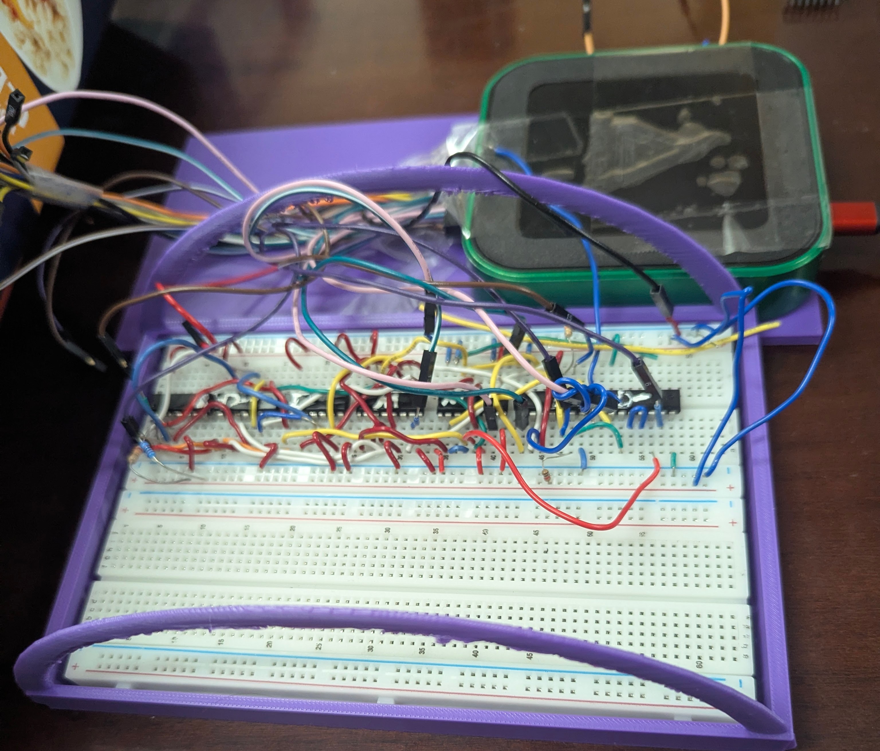
My Intro to Logic Design Final Project. A Breadboard State Machine for a simple vending machine controller.
Photos
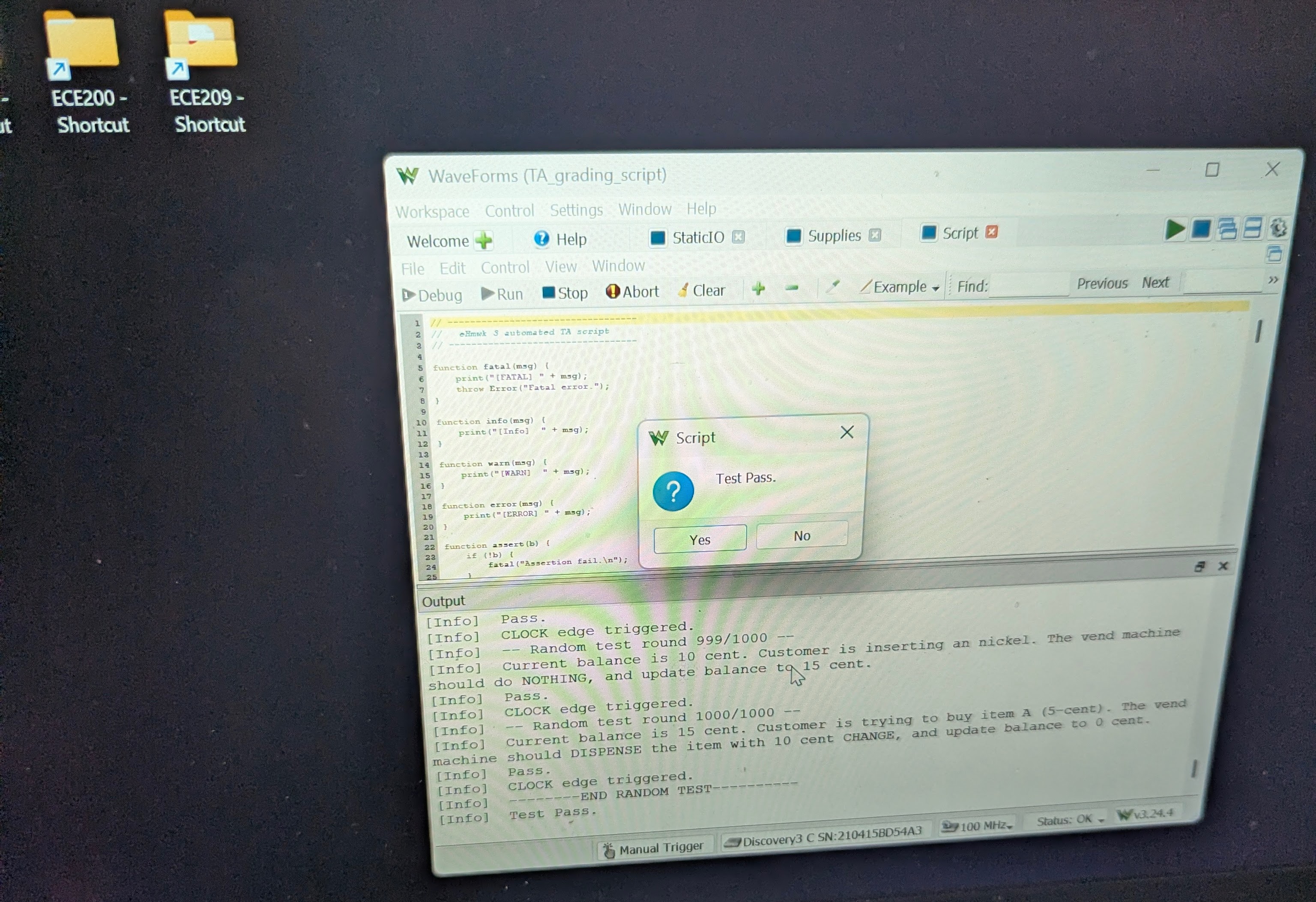
The benchmark that determines if the project has worked or not, running on Diligent Waveforms:
Write-up
This was the ultimate test for if we could interpret operation requirements, convert it into states on a big spreadsheet, turn that into simplified boolean expressions, and then optimize those to run on as few TTL gates as possible. That constraint being imposed by a desire to do as little wiring as needed.
Turning the requirements into a spreadsheet was a pretty standard task. Once the states and the inputs were identified and the impossible states were X (don’t care), filling the rest out was trivial. I decided to use Logism Evolution to find the minterms using their combinational analysis feature. Partially to reduce the chances of making a tedious mistake, but mostly because I like trying out new programs. Once the minterms were found for next state and outputs, I had it build the circuits and I connected them to each other and to the necessary memory elements (D Flip Flop). The circuit seemed quite cumbersome, and I knew that I had MUXes that could be used to cut down on gate count. I used OpenAI’s ChatGPT LLM to check if there are any low hanging fruit ways to use the TTL gates I had in my kit to do this. It proposed a circuit scheme in the form of a table. I manually built that scheme in Logism to test it. It worked well in the simulation, so I built it on my breadboard. I ran into a lot of issues, however. The simple ones were wiring mistakes where I put some wire-ends in the wrong slots. The ones that were more complex was troubleshooting what ended up being a faulty breadboard. The retaining metal on some rows was not making good contact with the wires I had. I ended up redoing the project on a new breadboard, scrapping a custom battery harness once I found out my Analog Discovery 3 could output the power necessary for the circuit, and made/printed a project holder to protect my delicate project. On demo day, my project passed the 1000 randomized test cases, and I went home feeling triumphant.